Centrifugal Pump Connection Diagram . Separated shafts are joined using a connection known as a coupling. learn about centrifugal pump diagram. some models of centrifugal pumps, like this one, will have a separate shaft for the pump and the motor. figure 1 is a simplified diagram of a typical centrifugal pump that shows the relative locations of. The impeller is a rotating. the main components of a centrifugal pump include the impeller, casing, suction and discharge connections, shaft, and bearings. Coupled pumps will usually have a bearing house which, as the name suggests, houses the bearings. In this article, we will learn the basic definition,. the centrifugal pump is the most widely used pump in the world. A brief overview of the centrifugal pump’s basic anatomy, and how a centrifugal.
from theengineeringmindset.com
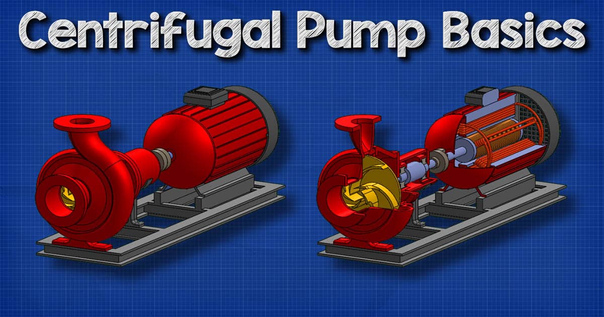
the main components of a centrifugal pump include the impeller, casing, suction and discharge connections, shaft, and bearings. the centrifugal pump is the most widely used pump in the world. In this article, we will learn the basic definition,. Separated shafts are joined using a connection known as a coupling. learn about centrifugal pump diagram. Coupled pumps will usually have a bearing house which, as the name suggests, houses the bearings. A brief overview of the centrifugal pump’s basic anatomy, and how a centrifugal. some models of centrifugal pumps, like this one, will have a separate shaft for the pump and the motor. The impeller is a rotating. figure 1 is a simplified diagram of a typical centrifugal pump that shows the relative locations of.
Centrifugal Pump Basics The Engineering Mindset
Centrifugal Pump Connection Diagram In this article, we will learn the basic definition,. the main components of a centrifugal pump include the impeller, casing, suction and discharge connections, shaft, and bearings. Coupled pumps will usually have a bearing house which, as the name suggests, houses the bearings. In this article, we will learn the basic definition,. learn about centrifugal pump diagram. figure 1 is a simplified diagram of a typical centrifugal pump that shows the relative locations of. A brief overview of the centrifugal pump’s basic anatomy, and how a centrifugal. The impeller is a rotating. some models of centrifugal pumps, like this one, will have a separate shaft for the pump and the motor. the centrifugal pump is the most widely used pump in the world. Separated shafts are joined using a connection known as a coupling.
From jmpcoblog.com
How to Pick a HVAC Centrifugal Pump Part 3 Mechanical Room Space and Centrifugal Pump Connection Diagram learn about centrifugal pump diagram. In this article, we will learn the basic definition,. the centrifugal pump is the most widely used pump in the world. some models of centrifugal pumps, like this one, will have a separate shaft for the pump and the motor. Coupled pumps will usually have a bearing house which, as the name. Centrifugal Pump Connection Diagram.
From circuitgonelladrianxm.z22.web.core.windows.net
Centrifugal Pump Schematic Diagram Centrifugal Pump Connection Diagram figure 1 is a simplified diagram of a typical centrifugal pump that shows the relative locations of. the centrifugal pump is the most widely used pump in the world. The impeller is a rotating. A brief overview of the centrifugal pump’s basic anatomy, and how a centrifugal. the main components of a centrifugal pump include the impeller,. Centrifugal Pump Connection Diagram.
From www.sintechpumps.com
Guide for Installing Centrifugal Pumps Sintech Pumps Centrifugal Pump Connection Diagram A brief overview of the centrifugal pump’s basic anatomy, and how a centrifugal. Separated shafts are joined using a connection known as a coupling. some models of centrifugal pumps, like this one, will have a separate shaft for the pump and the motor. the main components of a centrifugal pump include the impeller, casing, suction and discharge connections,. Centrifugal Pump Connection Diagram.
From www.youtube.com
Centrifugal pump series and parallel operations YouTube Centrifugal Pump Connection Diagram some models of centrifugal pumps, like this one, will have a separate shaft for the pump and the motor. the main components of a centrifugal pump include the impeller, casing, suction and discharge connections, shaft, and bearings. learn about centrifugal pump diagram. The impeller is a rotating. A brief overview of the centrifugal pump’s basic anatomy, and. Centrifugal Pump Connection Diagram.
From www.chemicalslearning.com
Centrifugal Pump Construction, Working, Advantages and Disadvantages Centrifugal Pump Connection Diagram figure 1 is a simplified diagram of a typical centrifugal pump that shows the relative locations of. Separated shafts are joined using a connection known as a coupling. the main components of a centrifugal pump include the impeller, casing, suction and discharge connections, shaft, and bearings. learn about centrifugal pump diagram. A brief overview of the centrifugal. Centrifugal Pump Connection Diagram.
From www.tapflopumps.co.uk
Industrial Self Priming Centrifugal Pump Tapflo Pumps UK Centrifugal Pump Connection Diagram In this article, we will learn the basic definition,. learn about centrifugal pump diagram. figure 1 is a simplified diagram of a typical centrifugal pump that shows the relative locations of. Coupled pumps will usually have a bearing house which, as the name suggests, houses the bearings. some models of centrifugal pumps, like this one, will have. Centrifugal Pump Connection Diagram.
From www.introtopumps.com
What is a Centrifugal Pump Intro to Pumps Centrifugal Pump Connection Diagram some models of centrifugal pumps, like this one, will have a separate shaft for the pump and the motor. The impeller is a rotating. Coupled pumps will usually have a bearing house which, as the name suggests, houses the bearings. A brief overview of the centrifugal pump’s basic anatomy, and how a centrifugal. learn about centrifugal pump diagram.. Centrifugal Pump Connection Diagram.
From ulsterdogfence.com
Centrifugal Pump Working and Types A Complete Guide (2023) Centrifugal Pump Connection Diagram the main components of a centrifugal pump include the impeller, casing, suction and discharge connections, shaft, and bearings. Separated shafts are joined using a connection known as a coupling. the centrifugal pump is the most widely used pump in the world. learn about centrifugal pump diagram. Coupled pumps will usually have a bearing house which, as the. Centrifugal Pump Connection Diagram.
From www.tec-science.com
How does a centrifugal pump work? tecscience Centrifugal Pump Connection Diagram Coupled pumps will usually have a bearing house which, as the name suggests, houses the bearings. some models of centrifugal pumps, like this one, will have a separate shaft for the pump and the motor. the main components of a centrifugal pump include the impeller, casing, suction and discharge connections, shaft, and bearings. A brief overview of the. Centrifugal Pump Connection Diagram.
From ar.inspiredpencil.com
Centrifugal Pump Diagram 2d Centrifugal Pump Connection Diagram A brief overview of the centrifugal pump’s basic anatomy, and how a centrifugal. The impeller is a rotating. Separated shafts are joined using a connection known as a coupling. In this article, we will learn the basic definition,. the centrifugal pump is the most widely used pump in the world. some models of centrifugal pumps, like this one,. Centrifugal Pump Connection Diagram.
From guidewiringhedgebill.z13.web.core.windows.net
Centrifugal Switch Wiring Diagram 11 Centrifugal Pump Connection Diagram the main components of a centrifugal pump include the impeller, casing, suction and discharge connections, shaft, and bearings. some models of centrifugal pumps, like this one, will have a separate shaft for the pump and the motor. the centrifugal pump is the most widely used pump in the world. figure 1 is a simplified diagram of. Centrifugal Pump Connection Diagram.
From www.scribd.com
BurksSeriesGNBCentrifugalPumpManual PDF Pump Electrical Wiring Centrifugal Pump Connection Diagram Coupled pumps will usually have a bearing house which, as the name suggests, houses the bearings. learn about centrifugal pump diagram. The impeller is a rotating. the main components of a centrifugal pump include the impeller, casing, suction and discharge connections, shaft, and bearings. Separated shafts are joined using a connection known as a coupling. figure 1. Centrifugal Pump Connection Diagram.
From www.tapflopumps.co.uk
CTH & CTI Centrifugal Pump Installation Tapflo Pumps UK Centrifugal Pump Connection Diagram In this article, we will learn the basic definition,. Separated shafts are joined using a connection known as a coupling. A brief overview of the centrifugal pump’s basic anatomy, and how a centrifugal. Coupled pumps will usually have a bearing house which, as the name suggests, houses the bearings. the centrifugal pump is the most widely used pump in. Centrifugal Pump Connection Diagram.
From ar.inspiredpencil.com
Centrifugal Pump Diagram Centrifugal Pump Connection Diagram In this article, we will learn the basic definition,. the centrifugal pump is the most widely used pump in the world. figure 1 is a simplified diagram of a typical centrifugal pump that shows the relative locations of. Coupled pumps will usually have a bearing house which, as the name suggests, houses the bearings. learn about centrifugal. Centrifugal Pump Connection Diagram.
From ryanmurphygleetvseriesmanila.blogspot.com
end suction pump diagram Octavio Blodgett Centrifugal Pump Connection Diagram the main components of a centrifugal pump include the impeller, casing, suction and discharge connections, shaft, and bearings. figure 1 is a simplified diagram of a typical centrifugal pump that shows the relative locations of. Separated shafts are joined using a connection known as a coupling. learn about centrifugal pump diagram. the centrifugal pump is the. Centrifugal Pump Connection Diagram.
From electricalworkbook.com
What is Centrifugal Pump? Working, Parts, Diagram & Types Centrifugal Pump Connection Diagram some models of centrifugal pumps, like this one, will have a separate shaft for the pump and the motor. Separated shafts are joined using a connection known as a coupling. The impeller is a rotating. the centrifugal pump is the most widely used pump in the world. figure 1 is a simplified diagram of a typical centrifugal. Centrifugal Pump Connection Diagram.
From www.sintechpumps.com
Guide for Installing Centrifugal Pumps Sintech Pumps Centrifugal Pump Connection Diagram A brief overview of the centrifugal pump’s basic anatomy, and how a centrifugal. The impeller is a rotating. learn about centrifugal pump diagram. the centrifugal pump is the most widely used pump in the world. In this article, we will learn the basic definition,. figure 1 is a simplified diagram of a typical centrifugal pump that shows. Centrifugal Pump Connection Diagram.
From www.pinterest.es
Technographic Important Parts of Centrifugal Pump on Ships Explained Centrifugal Pump Connection Diagram Separated shafts are joined using a connection known as a coupling. In this article, we will learn the basic definition,. figure 1 is a simplified diagram of a typical centrifugal pump that shows the relative locations of. learn about centrifugal pump diagram. some models of centrifugal pumps, like this one, will have a separate shaft for the. Centrifugal Pump Connection Diagram.